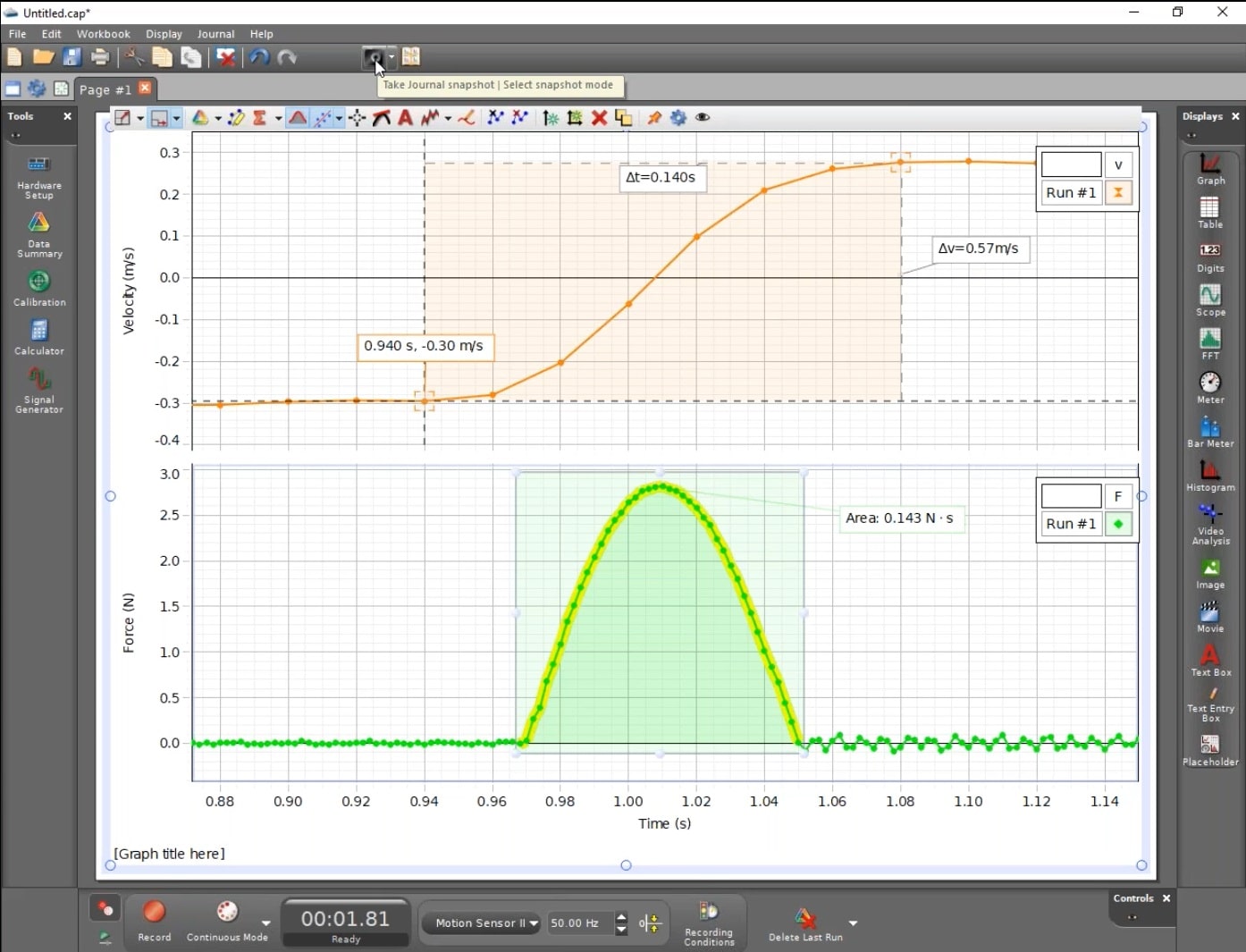
So let's begin monitoring and turn it on. And this time I am going to try to stop it approximately where the resonating frequency is. I'm going to run through that one more time.
#Pasco capstone stress strain data says nan generator#
So let's go ahead and turn off our signal generator and stop our monitoring. Afterwards there is no signal produced, so you shouldn't see anything in your oscilloscope. And we will just wait a second and watch the signal generator run through the entire 25 seconds. As I go beyond the resonating frequency, they go out of phase with each other, and my amplitudes begin to decrease. As I approach the resonating frequency, they go in to phase. You'll notice that I instantly have two different waves that come in to view in my oscilloscope. I am now ready to begin monitoring my voltages, so I am going to press the Monitor button, and I am going to turn my signal generator on. This will change the Record button to a Monitor button. The last thing I want to do is change my Record mode from Continuous to Fast Monitor. So that's approximately the scale I am going to be using. So, as you can see - approximately there - I am at a scale of 0 to 0.00008 seconds. So I am going to go and get a sample rate of approximately 5 MHz. Now for this particular set up, I am going to be using components that are resonating approximately around 30-35000 Hz. And what Capstone is trying to do is adjust the sample rate, so you are getting the maximum number of points to fill up your oscilloscope display. Now notice whenever I start adjusting my time axis, my sample rate is automatically changing along with it. I am also going to go ahead and adjust my time axis. So I am going to go ahead and adjust both of my y-axis ranges so that they max out near 3 V. I am also going to go ahead and adjust my axis. This will trigger on voltage from Channel A. I am going to go ahead and turn on my trigger. I am going to insert a second y-axis and add my Channel B Voltage Sensor. I am going to begin by adding Channel A to my left axis. So let's go ahead and get our Scope set up. Once your signal generator is set up, we can now go ahead and pin that to our screen, and open up a full-screen Scope beside it. We are going to start our initial frequency at 1000 Hz, our final frequency is going to be at 70000 Hz, over a duration of 25 seconds, in steps of 1 Hz. We are going to be using an amplitude of 3 V.

So let's go and turn on the single sweep. I am going to create a single sweep sine wave that's going to be looking at a range of frequencies across the circuit, hoping to find the resonating frequency for the LRC setup somewhere approximately in the middle of my time range. So I am going to click on my Signal Generator, and I will be using Output 1. I am now ready to go set up my signal generator. So I am going to add my two Voltage Sensors. I can do that by clicking on the channel, typing the first few letters of the sensor, and then confirming it with the Enter button. I am going to begin by going to my Hardware Setup and adding my two Voltage Sensors.

Now let's take a look PASCO Capstone and getting set up inside of our software. And my signal generator is attached across the entire circuit. In Channel B, I have a Voltage Sensor measuring the voltage across my second resistor. Connected to my 850 interface, in Channel A I have a Voltage Sensor measuring the voltage across the entire circuit. On the circuit board I am going to be using the first inductor component, the first capacitor component, and the second resistor component. I am going to be using the UI-5210 circuit board. Let's begin by taking a look at our LRC circuit setup. In this video, we are going to take a look at an LRC setup with PASCO Capstone and the 850 Universal Interface.


 0 kommentar(er)
